Electromagnetic Propulsion (EMP) technology’s potential for military applications are currently being explored by many nations. Magnetic-driven precision staging devices, large mass catapult launchers, low-speed and high-speed trains and cargo movers, high-speed long-range fire support naval guns, a high-speed satellite launches, and EMP-propelled ships and submarines are few of the applications that are currently being tried out. The discovery of the concept of Electromagnetic Propulsion was in 1889 by Prof. Elihu Thomson. In the 1960s E.R.Laitwaite developed the linear induction motor which used the application of the EMP.
Concept
Electromagnetic Propulsion (EMP) consists essentially of two components, one is the electromagnet where electricity is used to generate a magnetic field and the second is propulsion, the process of propelling (pushing) something. EMP, therefore, is the principle of accelerating an object by using the flow of magnetic field and current. When current flows through a conductor in a magnetic field, the conductor experiences a force in a direction perpendicular to the current and the magnetic field known as Lorenz Force. If a fluid such as a gas or liquid is used instead of the conductor for the propulsion, it is called Magneto Hydro Dynamic drive.
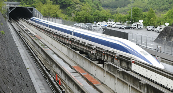
Magnetic Levitation (Maglev)
The principle of a linear motor and the property of magnetic repulsion is used in Maglev trains. The first patent on magnetic levitation transportation system was granted to James Powel and Gordon Danby in 1966, which proposed superconducting Maglev transportation. The first maglev system in the world worked between Birmingham International airport and Birmingham Railway station in the 1990s.
Propulsion of a maglev train is caused by a linear motor, which has all 3 elements of a conventional Direct Current (D.C) motor, ie; stator, rotor and commutator. If the conventional D.C motor is opened and flattened out, it becomes a linear conceptually. In a maglev system, the track becomes the poles alternating between north and south poles along the length of the track, a solenoid that is propelled along the track (the train) and a commutator to change the poles sequentially. The solenoid can be replaced by permanent magnets.
There are three types of magnetic propulsion are used for maglev as explained below.
a) Propulsion by Linear Induction Motor
In propulsion by linear induction motor (LIM), the armature becomes the primary winding and the field the secondary winding. The primary (armature) is externally excited and its magnetic field induces currents in the field windings. The primary windings are distributed such that when excited by a 3 phase supply, a travelling field is generated which has forward, backward and pulsating components. The secondary is either a metallic cage or short-circuited 3 phase winding. The current, the primary magnetic field induces into the secondary generates a reactive magnetic field. The interaction of the two fields produces a motion that can be controlled by regulating the phase of the primary current. The armature current can be regulated to control the thrust speed or position. Bearings are used to restrict the motion into a longitudinal single degree of freedom. The LIM where the stator coils are on board is called ‘Short Primary’’ type and where the stator coils are on the guideway and the conducting sheets are on board is called ‘Long Primary” type. LIM is used for urban transportation in Japan and similar systems are in use in Malaysia, Canada, New York airport access system etc. LIM requires complex drives to get levitation and causes oscillation.
b} Linear Synchronous Motor Propulsion
The motion of a linear synchronous motor (LSM) is in synchronism with the travelling field produced by a polyphase armature that is excited by either ac or switched current. The field can be a permanent magnet or variable reluctance system. The propulsion and levitation modules are located on each side of the train. Each module contains the exciting field magnets of the LSM which works as the levitation magnets as well. This system is good for high-speed applications.
c) Propulsion by Permanent Magnets
Permanent magnets have been successfully applied to linear synchronous drives for short distances and for transportation systems in factories etc. In this system, permanent magnets create the field. The thrust force is generated when the field of the magnets tend to align itself with the travelling field of the armature.
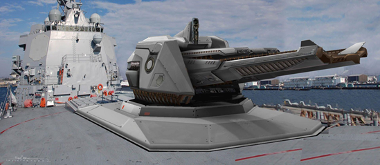
Electromagnetic Railguns (EMRG)
Conventional guns use explosives to get the expansion of the gas for launching the projectile. It has limitations of launch velocity and range. Another problem is the safety issue of storing large quantities of explosives. EMRG has advantages over the conventional gun such as enhanced safety as there is no explosive, faster hitting of targets, increased range etc and is a good choice for the Navy.
A railgun consists of two parallel metal rails connected to an electric power supply. When a conductive projectile is inserted between the rails the magnetic circuit is completed through it.
The rails become electromagnets and a flux density of the order of 10 Tesla is developed. The current in the rails is in opposite direction. The net magnetic field acts at the right angle to the plane of the rails and produces a Lorenz Force to accelerate the projectile. The force also tries to pull apart the rails and therefore the rails need rigid mounting. EMRG is capable of launching projectiles weighing several kilograms at speeds of Mach 7.
The electrical energy to the railgun is given from charged capacitor banks kept near the gun. The charging of the capacitor bank is from a dedicated power supply from the ship’s generator system. For launching heavy projectiles over a long distance, the electric power requirement is high. For example, a capacitor bank capable of 10 megajoules capacity can fire 1kg projectile at a speed of 3000 m/sec.
Some of the problems of railguns are: –
-The capacitors occupy large space and require maintenance.
-Dedicated power source is required for charging the capacitor bank.
-The rails may get overheated by the high current and the friction from the projectile.
-The electromagnetic field emission from the operation of the gun can be detected by the enemy and require efficient shielding to prevent it.
.
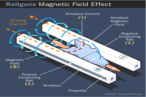
Fig 1- Schematic Diagram of Railgun
Electric Propulsion Systems for Space applications
The use of electric power enhances the propulsive performance of thrusters used for various space and military applications. Electric Propulsion requires very little mass when compared to the chemical system to accelerate a mass. Some of the technologies are given in this section.
a) Gridded Ion Thruster
In this system, ions are accelerated by electrostatic forces. The electrodes placed at the downstream end of the thruster generate the electric field required for the acceleration. All electrodes have a number of coaxial apertures which act as lenses that electrically focus ions. The upstream electrode is the accelerator grid and is positively charged and the downstream electrode is negatively charged. The ions are attracted towards the accelerator grids creating thousands of ion jets. The exhaust velocity of the ions in the beam is based on the voltage applied.
b) Hall Effect Thruster
Hall Effect Thruster uses the electrostatic potential to accelerate ions to high speeds. The negative charge is provided by the plasma at the open end of the thruster. A radial magnetic field of about 0.03 Tesla is used to confine the electrons. A propellant such as xenon gas is fed through the anode which is diffused into the channel of the thruster where it is ionized by the high energy electrons. The xenon ions are accelerated between the anode and cathode.

Fig- 2 Schematic Diagram of Hall Effect Thruster
c) High Efficiency Multistage Plasma Thruster
This is developed by THALES Electron Devices, Germany, which uses the ion thruster principle. Its propellant consumption is less than 20 % of the chemical system. In this system, low energy neutralizer electrons are confined by magnetic exit cusp and maintain a low plasma potential at the thruster end. A few of these electrons find their way from the neutralizer through the exit cusp of the discharge channel. These electrons are trapped in spirals along their bent magnetic flux lines. The strong magnetic field gradient in the radial direction reflects the electrons like a magnetic mirror. The plasma is achieved by permanent magnets and hence there is no discharge channel erosion.
d) Pulse Plasma Thruster
Pulse Plasma Thruster is the simplest of electric propulsion systems. The Soviet space probe used it in the 1960s.
In this system, an arc is sent through a fuel which turns it into plasma. The plasma is sent through two charged plates energized by capacitors and the plasma gets charged and creates a flow of electrons.
This creates a strong electromagnetic field and exerts a Lorenz Force on the plasma accelerating it out of the exhaust at high velocity. Its operation is similar to the railgun in principle.
e) Magneto Plasma Dynamic Thruster
This works on the principle of the Lorenz Force. There is no combustion of fuel. A gaseous material (Xenon, Neon, Argon etc) is ionized and fed into an accelerator chamber, where the magnetic and electric fields are created by a power source. The ionized particles are propelled through the exhaust chamber creating the thrust.
f) Field Emission Electric Propulsion
This is an electrostatic propulsion concept that uses metal ions such as cesium, indium, etc. A potential difference of several kilovolts is applied between an emitter and accelerator electrodes which accelerates the ions at high velocities. This system is used for precise altitude and direction controls of satellites.
g) Quad Confinement Thruster
Eight electromagnets are arranged to create a convex magnetic field with a central cusp and 4 outer cusps along the periphery. The thrust is produced by the momentum of ions accelerated through a Hall Effect static field.
Conclusion
A brief description of the Maglev, Railgun and other propulsion systems is given in this paper. Electromagnetic Propulsion has a wide range of applications including industries, military, and space crafts. Military applications being explored are direct-fire tank guns, long‐range artillery, and missile launch. Electromagnetic Propulsion would be the key technology enabler for all-electric naval ships and submarines in the future.
References
- Kamhawi. H, Arrington. IA, et al. ‘Performance evaluation of a High Energy Pulsed Plasma Thruster’ AIAA- 2005-3695. 41st Joint Propulsion Conference, Tuscon, AZ, July 2005
- T. Froehlich, “RITA, High-Efficiency Long Life Radio Frequency Ion Thruster”. EADS International Technology Conference 2003, Paris, France.
- H. Bassner et al, “Development Steps of RF Ion Thruster- RIT -37th Joint Propulsion Conference and Exhibition”-2001, Salt Lake City, Utah.
- Kazuo. S, “Magnetic Levitation Technologies: Railway Technology Today”- Review pp 58-60. www.rtri.or.jp
- J. Gallant, E. Vanderbeke et al, “Design Considerations for an Electromagnetic Railgun to be used against anti ship missiles” IEEE Transactions on Plasma Science Vol 41, No 10, pp 2800-2804, 2013.
- Title Image source 1 : https://forum.nasaspaceflight.com/